|
DISTILLATION
COLUMN DESIGN
|
|
As mentioned, distillation columns
are designed using VLE data for the
mixtures to be separated. The vapour-liquid equilibrium characteristics
(indicated by the shape of the equilibrium curve) of the mixture
will determine the number of stages, and hence the number of trays,
required for the separation. This is illustrated clearly by applying
the McCabe-Thiele method to design a binary column.
|
| McCABE-THIELE
DESIGN METHOD |
|
The
McCabe-Thiele approach is a graphical one, and uses the VLE plot
to determine the theoretical number of stages required to effect
the separation of a binary mixture. It assumes constant
molar overflow and this implies that:
|

|
molal heats of vaporisation of the components are roughly the
same |

|
heat effects (heats of solution, heat losses to and from column,
etc.) are negligible |

|
for every mole of vapour condensed, 1 mole of liquid is vaporised |
| The design procedure is simple. Given the VLE diagram
of the binary mixture, operating lines are drawn first. |

|
Operating lines define the mass balance relationships between
the liquid and vapour phases in the column. |

|
There is one operating line for the bottom (stripping) section
of the column, and on for the top (rectification or enriching)
section of the column. |

|
Use of the constant molar overflow assumption also ensures the
the operating lines are straight lines. |
| |
Operating Line for the Rectification
Section |
| |
The
operating line for the rectification section is constructed
as follows. First the desired top product composition is located
on the VLE diagram, and a vertical line produced until it intersects
the diagonal line that splits the VLE plot in half. A line with
slope R/(R+1) is then drawn from
this instersection point as shown in the diagram below.
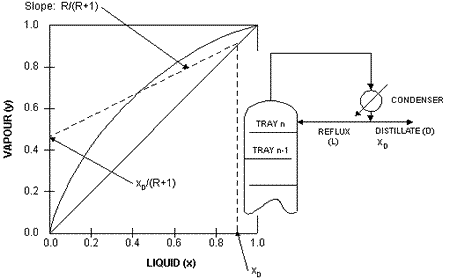
R
is the ratio of reflux flow (L)
to distillate flow (D) and is called
the reflux ratio and is a measure
of how much of the material going up the top of the column is
returned back to the column as reflux.
|
| |
Operating Line
for the Stripping Section |
| |
The
operating line for the stripping section is constructed in a similar
manner. However, the starting point is the desired bottom product
composition. A vertical line is drawn from this point to the diagonal
line, and a line of slope Ls/Vs
is drawn as illustrated in the diagram below.
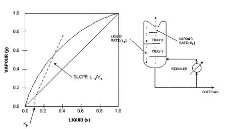
Ls
is the liquid rate down the stripping section of the column,
while
Vs
is the vapour rate up the stripping section of the column. Thus
the slope of the operating line for the stripping section is
a ratio between the liquid and vapour flows in that part of
the column.
|
| |
Equilibrium and
Operating Lines |
| |
The
McCabe-Thiele method assumes that the liquid on a tray and the
vapour above it are in equilibrium. How this is related to the
VLE plot and the operating lines is depicted graphically in the
diagram on the right.
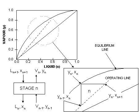
A
magnified section of the operating line for the stripping section
is shown in relation to the corresponding n'th stage in
the column. L's are the liquid flows while V's are the vapour
flows. x and y denote liquid and vapour compositions and the
subscripts denote the origin of the flows or compositions.
That is 'n-1' will mean from the stage below stage
'n' while 'n+1' will mean from the stage above
stage 'n'. The liquid in stage 'n' and the vapour above
it are in equilibrium, therefore, xn and yn
lie on the equilibrium line. Since the vapour is carried to
the tray above without changing composition, this is depicted
as a horizontal line on the VLE plot. Its intersection with
the operating line will give the composition of the liquid
on tray 'n+1' as the operating line defines the material balance
on the trays. The composition of the vapour above the 'n+1'
tray is obtained from the intersection of the vertical line
from this point to the equilibrium line.
|
| |
Number
of Stages and Trays |
| |
Doing
the graphical construction repeatedly will give rise to a number
of 'corner' sections, and each section will be equivalent to a
stage of the distillation. This is the basis of sizing distillation
columns using the McCabe-Thiele graphical design methodology as
shown in the following example.
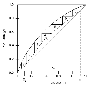 Given the operating lines for both stripping
and rectification sections, the graphical construction described
above was applied. This particular example shows that 7 theoretical
stages are required to achieve the desired separation.
The
required number of trays (as opposed to stages) is one
less than the number of stages since the graphical construction
includes the contribution of the reboiler in carrying out the
separation.
The
actual number of trays required is given by the formula:
-
(number
of theoretical trays)/(tray efficiency)
Typical
values for tray efficiency ranges from 0.5 to 0.7 and depends
on a number of factors, such as the type
of trays being used, and internal liquid and vapour flow
conditions. Sometimes, additional trays are added (up to 10%)
to accomodate the possibility that the column may be under-designed.
|
| |
The
Feed Line (q-line) |
| |
The
diagram above also shows that the binary feed should be introduced
at the 4'th stage. However, if the feed composition is such that
it does not coincide with the intersection of the operating lines,
this means that the feed is not a saturated liquid. The condition
of the feed can be deduced by the slope of the feed
line or q-line. The q-line
is that drawn between the intersection of the operating lines,
and where the feed composition lies on the diagonal line.
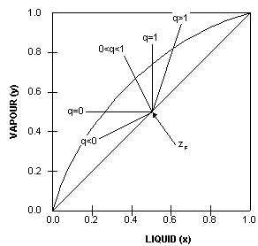
Depending on the state of the feed, the feed lines will have
different slopes. For example,
-
q
= 0 (saturated vapour)
-
q
= 1 (saturated liquid)
-
0
< q < 1 (mix of liquid and vapour)
-
q
> 1 (subcooled liquid)
-
q
< 0 (superheated vapour)
The
q-lines for the various feed conditions are shown in the diagram
on the left.
|
| |
Using
Operating Lines and the Feed Line in McCabe-Thiele Design
|
| |
If
we have information about the condition of the feed mixture, then
we can construct the q-line and use it in the McCabe-Thiele design.
However, excluding the equilibrium line, only two other pairs
of lines can be used in the McCabe-Thiele procedure. These are:
-
feed-line
and rectification section operating line
-
feed-line
and stripping section operating line
-
stripping
and rectification operating lines
This
is because these pairs of lines determine the third.
|
|
OVERALL
COLUMN DESIGN
|
|
Determining
the number of stages required for the desired degree of separation
and the location of the feed tray is merely the first steps in
producing an overall distillation column design. Other things
that need to be considered are tray spacings; column diameter;
internal configurations; heating and cooling duties. All of these
can lead to conflicting design parameters. Thus, distillation
column design is often an iterative procedure. If the conflicts
are not resolved at the design stage, then the column will not
perform well in practice. The next set of notes will discuss the
factors that can affect distillation column performance.
|

